Lighting Selection
AS manufacturing technology has advanced in recent years, various products can be mass-produced in a short period of time. As a result, “product inspections” are no longer able to keep up with visual inspections by humans due to the demand for higher accuracy, inspection speed, and difficulty in training new employees. Replacement of visual inspection is underway with machine vision (image processing equipment), which inspects products for defects based on image data captured by industrial cameras and lenses.
Machine vision has many advantages, such as 24-hour operation, programmable operation, and reduced variation in inspection results. However, machine vision is not simply a matter of installing cameras. In fact, the human eye excels in its ability to constantly focus on a product depending on its distance and viewing angle, and it is able to recognize both bright and dark areas in a single glance. It can flexibly respond to any given situation. In contrast, machine vision often requires a single image of the product being delivered by a fixed camera, lens, and lighting, and unless the defective part is clearly visible in the image, it is impossible to correctly determine whether the product passed or failed.
This is the first step toward stable machine vision operation.
What is a good image?
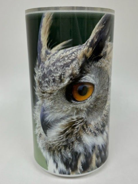
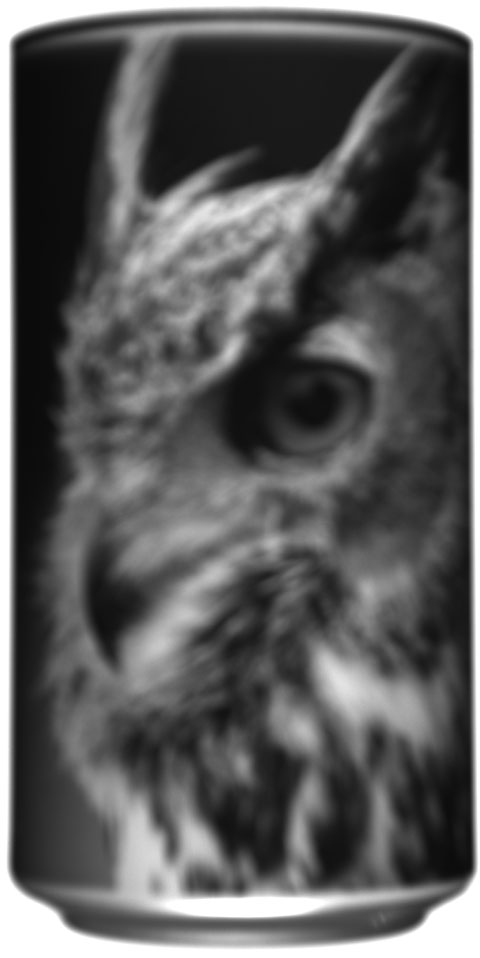
There is a cylindrical container with a picture of a bird printed on it.
Let’s capture an image of this with a combination of lens + camera +lighting.
What is the difference between a good image and a bad image?
There are four main factors
VSTdefines as the conditions for a good image.
- ❶ Resolution
- ❷ Focus
- ❸ Contrast
- ❹ Brightness uniformity
To obtain a good image,
let’s look at 4 important factors in camera + lens + lighting from bad examples.
-
❶ Resolution
Poor resolution leads to “not being able to see what you want to see.”
To make it a good image
Select a camera / lens with a resolution appropriate for the accuracy you wish to detect.
-
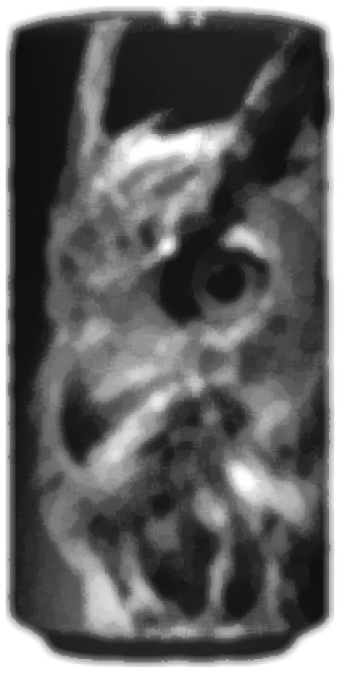
❷ Focus
Without the correct focus, the overall image will be blurred.
To make it a good image
The basic idea is to focus on the object by adjusting the depth of field with the aperture and brightness of the lighting.(In some cases, the image may be intentionally blurred.)
-
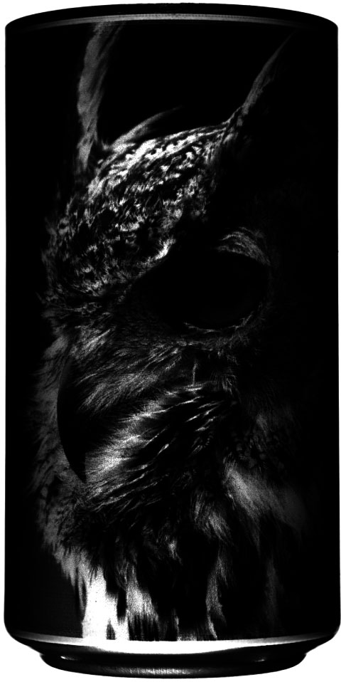
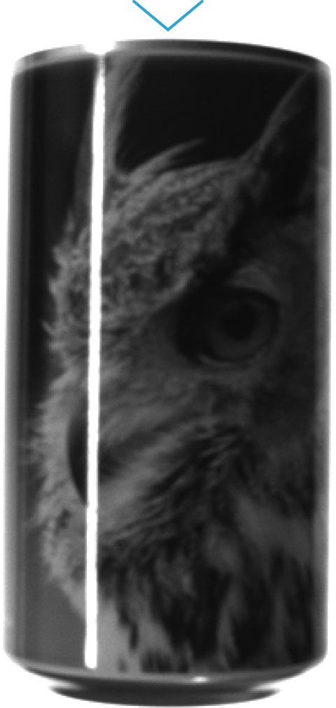
❸ Contrast
Lack of contrast between black and white results in an unclear image.
To make it a good image
Adjust the brightness of the lighting and the shutter speed of the camera to clearly define the areas you want to emphasize and those you prefer not to.
-
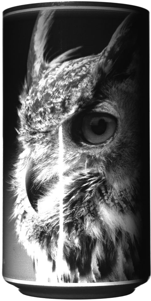
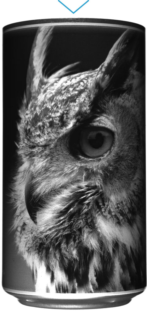
❹ Brightness uniformity
The lighting is uneven on both sides and top and bottom, and the lighting is partly reflected in the image making it too bright.
To make it a good image
Lighting should be adequate for the object and from the appropriate position.

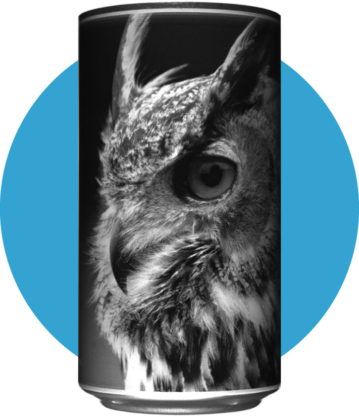
- ❶ Resolution
- ❷ Focus
- ❸ Contrast
- ❹ Brightness uniformity
By being aware of all the four aspects comprehensively,
you can produce a quality image such as the one on the left.
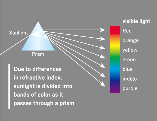
Relation between the color of light and the color of objects
The image obtained depends on what color of lighting is applied to the color of the target subject.
The Three Primary Colors of Light
The three most basic colors are Red, Green, and Blue and are represented by the acronym RGB.
Mixing the three colors of light in equal proportions produces white light.
Indoor lighting such as fluorescent lamps and sunlight appear white because the various colors of light are mixed in proportion to each other.
In addition, almost any color can be produced by controlling the balance of RGB.
Color visibility of objects
The color of an object is determined by the color of the light that reaches the object from a light source, such as the sun, and is reflected without being absorbed by the object.
(Example 1)
If white light is shined on a red apple, it will appear red because it absorbs blue and green light and reflects only red.
f green light is shined on a red apple, it absorbs green and reflects no color, making it appear black.
(Example 2)
When white light is shined on a yellow banana, it absorbs blue light and retlects a mixture of red and green light, making it appear yellowish.
“If you shine blue light on a yellow banana, it absorbs blue and appears blackish because it absorbs blue.

The clarity of an object is determined by the color of its light.
Using this property, we can control whether an object is “brightened” or “darkened” by using monochromatic lighting on a colored object.
“In fact, using a monochrome camera and lighting a red (R) green (G) and blue (B) object with each color of red (R), green (G), and blue (B) will produce the following image.


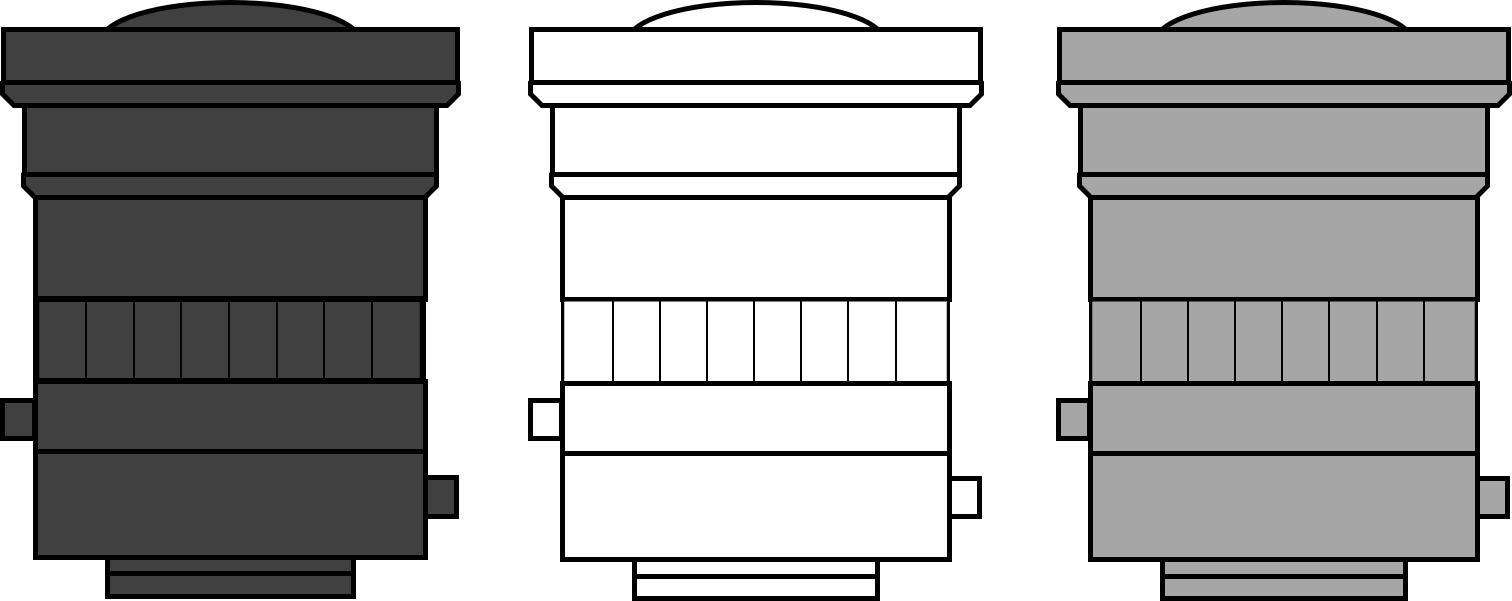
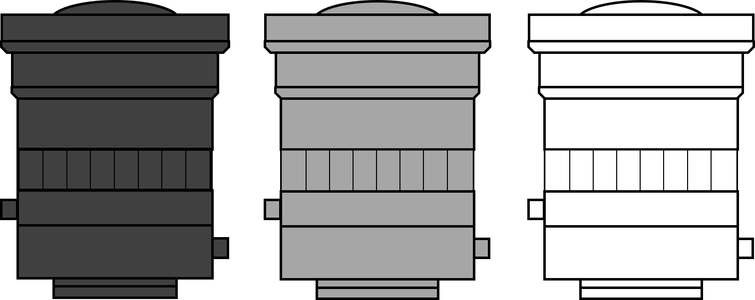
As shown above, when the light source color that includes the color of the object is irradiated, the object can be imaged brightly (white).
Conversely, if the object is illuminated by a light source color that does not include the object’s color, the object can be imaged dark (black).
The same property can be used to “darken/lighten” defects (scratches and stains) on an object.
(Example 3)
When detecting blue stains on a red object, red lighting can be used to capture the object brighter and the stain darker, resulting in a high-contrast image.
In addition to highlighting defects, the same concept of lighting selection can be used to eliminate excess background or unnecessary objects.
*Color cameras often use white lighting to take advantage of this feature.
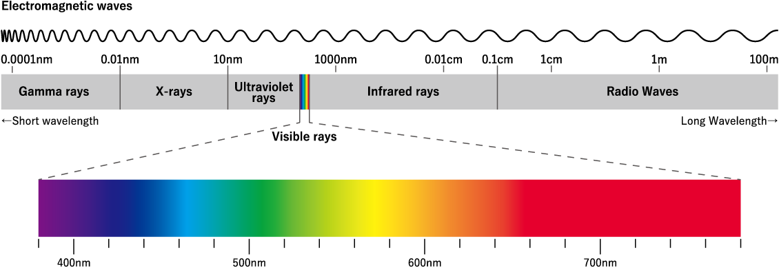
Light wavelength
“Light” is a class of waves called electromagnetic waves.
The range of this light that the human eye can perceive is called “visible light” and extends from about 380 nm to 780 nm (nanometers).
The wavelength range used in imaging is even wider than visible light, ranging from ultraviolet to infrared.
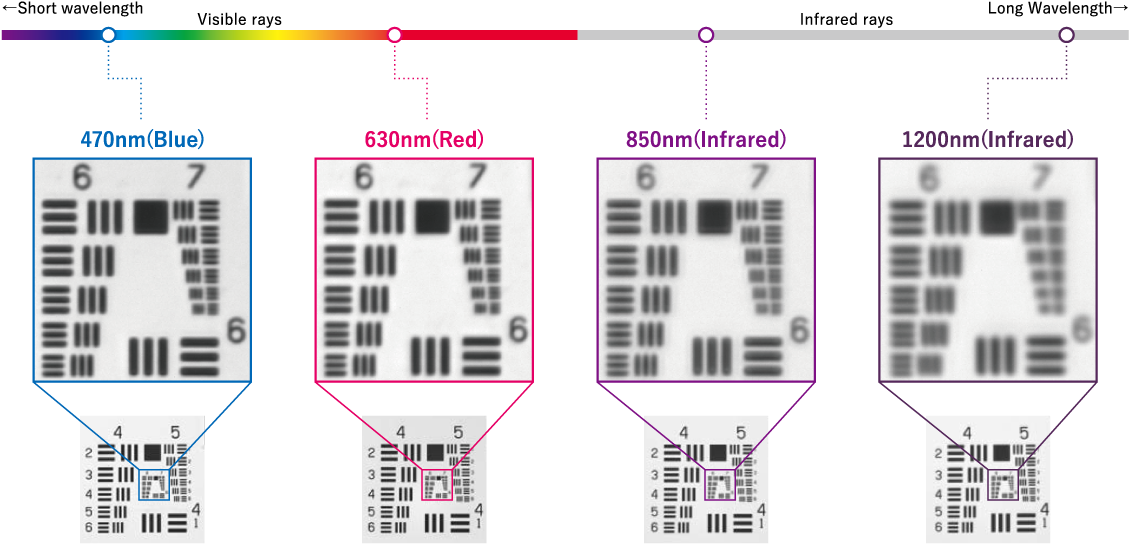
Wavelength and Resolution
This characteristic leads to differences in refractive indices in lenses, and especially in the case of lenses with high magnification, the wavelength of the light source has a noticeable effect on the resolving power of the image.
δ(μm)=0.61 × λ / NA
(λ=wavelength、NA=lens aperture)
Resolution is expressed by the above formula, but if the same lens (same NA) is used, the longer the wavelength, the greater the spatial resolution=less finely resolved.
If you want to image a small workpiece at high resolution, it is necessary to carefully select the wavelength of the lighting and the numerical aperture of the lens.
Ultraviolet and infrared light
Among wavelengths invisible to the human eye, wavelengths shorter than visible light are called “ultraviolet light” and longer wavelengths are called “infrared light”.
(See the figure on the previous page.)
it is necessary to use different wavelengths depending on the object.
Image captured by ultraviolet light
Exposure of certain objects, including phosphors, to ultraviolet light causes a fluorescence phenomenon (excitation) that absorbs the ultraviolet light and emits light with a longer wavelength.
This allows the position of objects that are difficult to recognize with visible light to be captured more easily.
-
Visible light
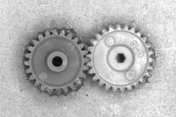 Unable to tell where the gear is coated with grease.
-
Ultraviolet light (UV light)
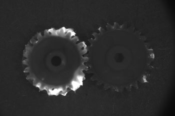 Grease is protruded and the applied area is clearly recognizable
-
Visible light
 Crumbs are mixed with foreign objects of the same color, which cannot be distinguished by visible light.
-
Ultraviolet light (UV light)
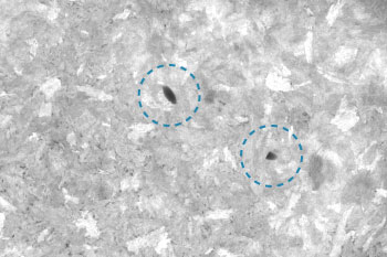 Crumbs stand out and become brighter, while foreign objects can be kept dark.
Image captured by infrared light
It can transmit through specific objects. This allows detection of substances within the object that are not visible with visible light.
It can also darken and detect areas that contain more moisture than their surroundings, due to the absorption properties of moisture in a specific wavelength range of infrared light.
Infrared transmittance:
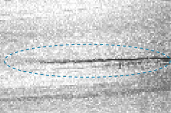
Distinguishes between wood grain and cracks
-
Visible light (blue)
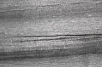
-
Infrared light (IR light)
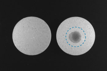
Moisture detection:
Water droplets on tablet confectionery
-
Visible light
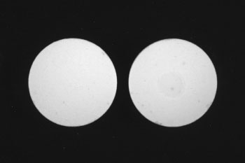
-
Infrared Ilight (IR light)
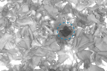
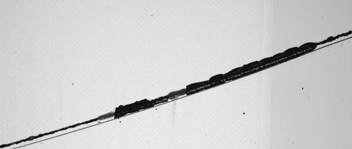
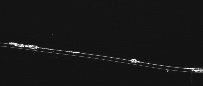
Infrared transmission + moisture detection:
Water droplets of dried wakame seaweed
-
Visible light
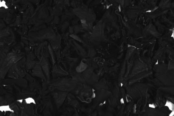
-
Infrared light (IR light)
Infrared transmission + moisture detection:
Scratches on eggplant
-
Visible light
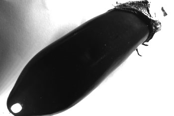
-
Infrared light (IR light)
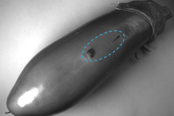
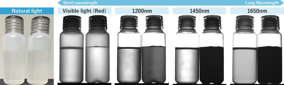
There is no difference under natural and visible light, but as we move to longer wavelengths, the water appears blacker and the difference becomes clearer.
Bright field and dark field
A rough, low-reflective workpiece such as paper or untreated wood will appear equally bright no matter where the light is projected.
On the other hand, a workpiece that is shiny and highly reflective, such as a mirror, polished metal or glass, is captured in a completely different image depending on where the light is projected from.
Dark field: Capturing the diffuse reflection of light irradiated on a workpiece. It also captures diffuse transmitted light transmitted through a translucent object such as an acrylic plate.
What you want to capture: flaws on the panel
-
Bright field/Lighting: Spot light

-
Dark field/ Lighting: Low angle ring light
What you want to capture: Fingerprints and smudges on the glass part
-
Bright field of view / Lighting: Flat light
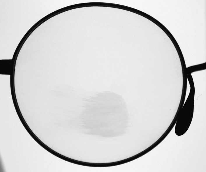
-
Dark field/ Lighting: Low angle ring light
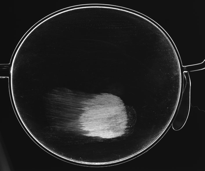
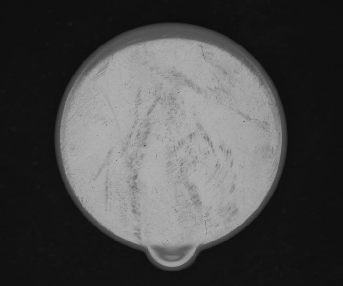
What you want to capture: Surface flaws
-
Bright field/ lighting: Box coaxial light
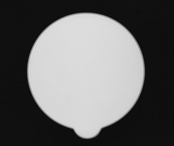
-
Dark field / Lighting: Diffused ring light
What you want to copy: How cleanly is the logo printed?
-
-
Dark field / Lighting: Bar light
Irradiation solid angle
When the workpiece surface is uneven, the following patterns can be used for imaging.
(1) When you want to make the unevenness stand out as a defect.
(2) When you do not want the unevenness to stand for defects, but want to detect other stains, etc.
It is necessary to obtain completely different results for (1) and (2), which can be achieved by adjusting the “irradiation solid angle”
The irradiation solid angle is the angle of incident light to a point on an object, and the size of the irradiation solid angle controls the appearance of unevenness.
→ Place lighting at a distance with a small light-emitting surface. (Smaller irradiation solid angle)
→ Use lighting with a large light-emitting surface at a closer distance to minimize the visibility. ( Larger irradiation solid angle)
This is also an essential tactor to consider when using a backlight to capture the silhouette of the object.
-
Large irradiation solid angle
Cannot see the strike-conformity of the metal workpiece.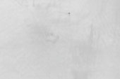
- Dome light +coaxial light at close proximity to the workpiece

-
Small irradiation solid angle
Unevenness is emphasized, and the dents can be extracted.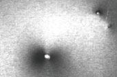
- Coaxial light at a distance from the workpiece

-
Large irradiation solid angle
Unevenness makes it difficult to see foreign objects.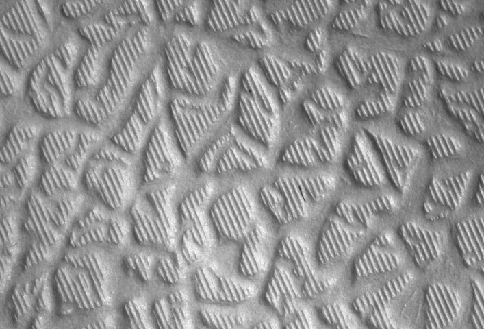
- Narrow bar light from an angle

-
Small irradiation solid angle
Remove unevenness and extract foreign objects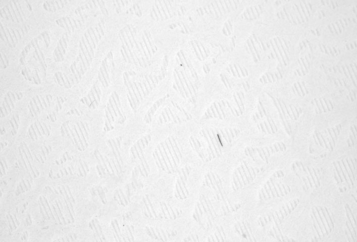
- Dome light close to the workpiece

-
Large irradiation solid angle
Image captured with a backlight does not capture the silhouette well due to light diffusion.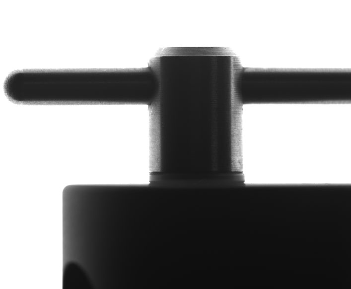
- Backlight larger than the workpiece at close proximity to the workpiece

-
Small irradiation solid angle
Suitable for dimensional measurement, etc., as light diffusion is minimal and the silhouette can be clearly recognized.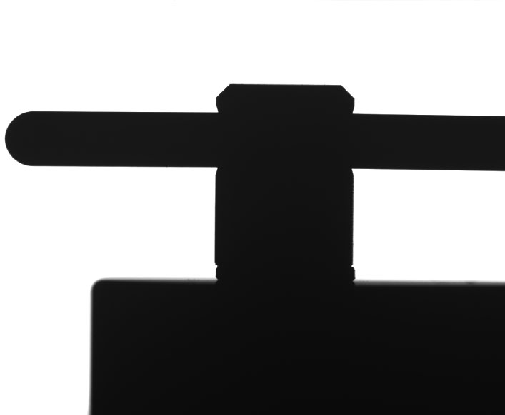
- Backlight slightly larger than the workpiece positioned at a distance from the workpiece

As described above, the color, type, size, and installation method of lighting can change the way an object is seen. The selection of the lighting is essential together with the camera and lens.
VS Technology offers verification with actual objects, so please contact us for more information.
